Years ago I really liked flight simulators. Since I was a child I have liked airplanes a lot, so I guess it came from there. I have many simulators, but the truth is that I have never spent much time playing. And now I don’t either. Even so, I have installed the DCS (the top of the range simulator that there is today) and a HOTAS Joystick. When I play, I use to do it with Su-25T.
Since I don’t play much, it often happens that I forget the keys to control the plane. This causes it to open the parachute when what it wanted to open was the airbrake, or something like that.
So one day I thought it would be cool to have some kind of external controller that had a few named buttons to control some of those commands.
I found on internet that there are people who make their own controllers. There are even those who make their own entire cockpit. I prefer something simpler. I did a lot of research to see how all this was done. I did a basic electronics course (although it is simpler than it seems). I even built a very simple first prototype to see if it could work.
When I knew everything I had to do to build it, I bought the materials and got to work. During the construction numerous problems arose, but once solved, this is the result.
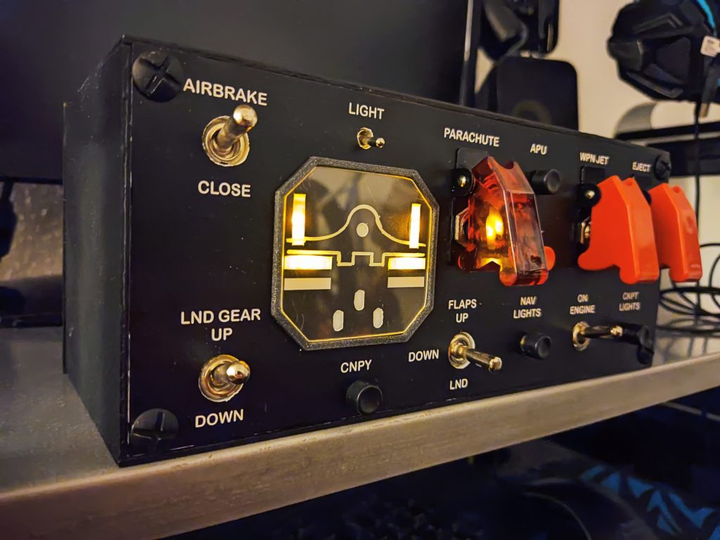
Contrary to what is usual, I have not built a replica of a panel as is in the real plane. What I have built is a mixed panel, which has the most interesting controls to me.
Also, I have not followed any special order to place the controls. Mainly I have put them in a way that I liked the result. I have only tried to group those that act on certain LEDs that show the status of the flaps, airbrake and landing gear.
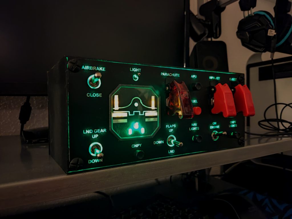
I leave you a short video and then I’ll tell you more details about the panel.
Some features:
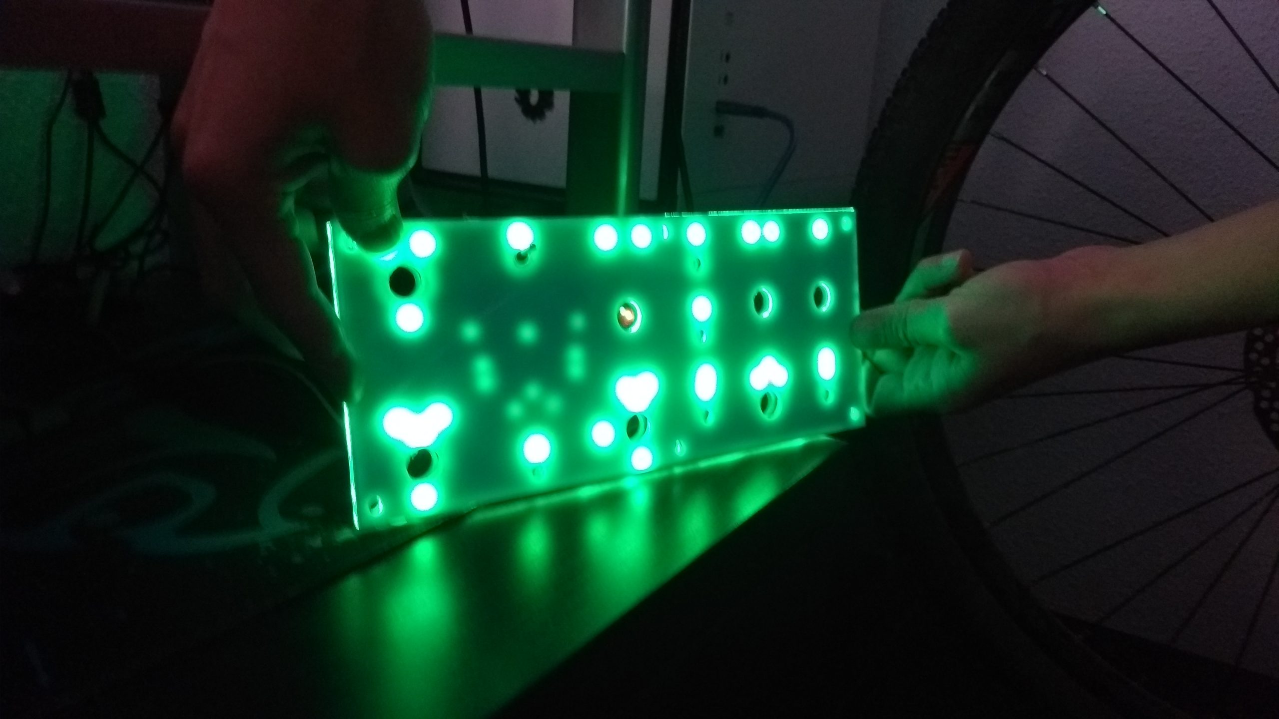
It is backlited. It has lights inside that illuminate the white letters on the front, so that if I play in the dark, I can see the texts. There is a switch to turn this lighting on and off.
It is easily removable in case something needs to be adjusted or fixed. Front and back cover can be removed.
Everything works with a single Arduino board. That is, there is no separate circuit (with its own power supply) for the backlight, or for the LEDs. Everything works with the 5v that the arduino can provide. There is only one wire coming out of the panel; a USB that goes to the computer.
And I’ve tried to make it as cheap as possible. Even so, this one in particular has not been cheap, since I have spent a lot of money on tests and material that I finally have not used.
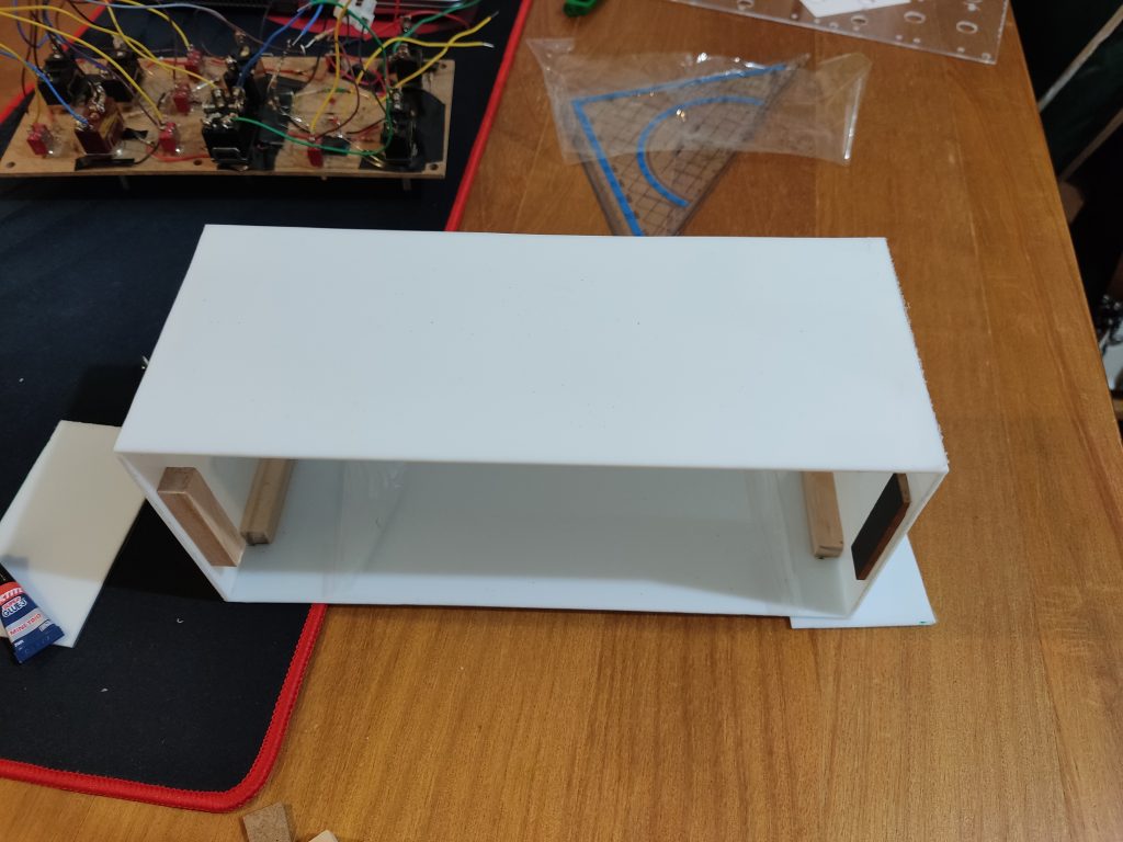
The box is white methacrylate painted black (the sides and the back). I have cut the pieces of the sides and glued them. The rear panel is not glued. It has some wooden slats glued inside just to the size of the inside of the box. This makes it «fit» and not move. On one of the sides I have cut the methacrylate to be able to pass the cable that goes to the USB of the computer.
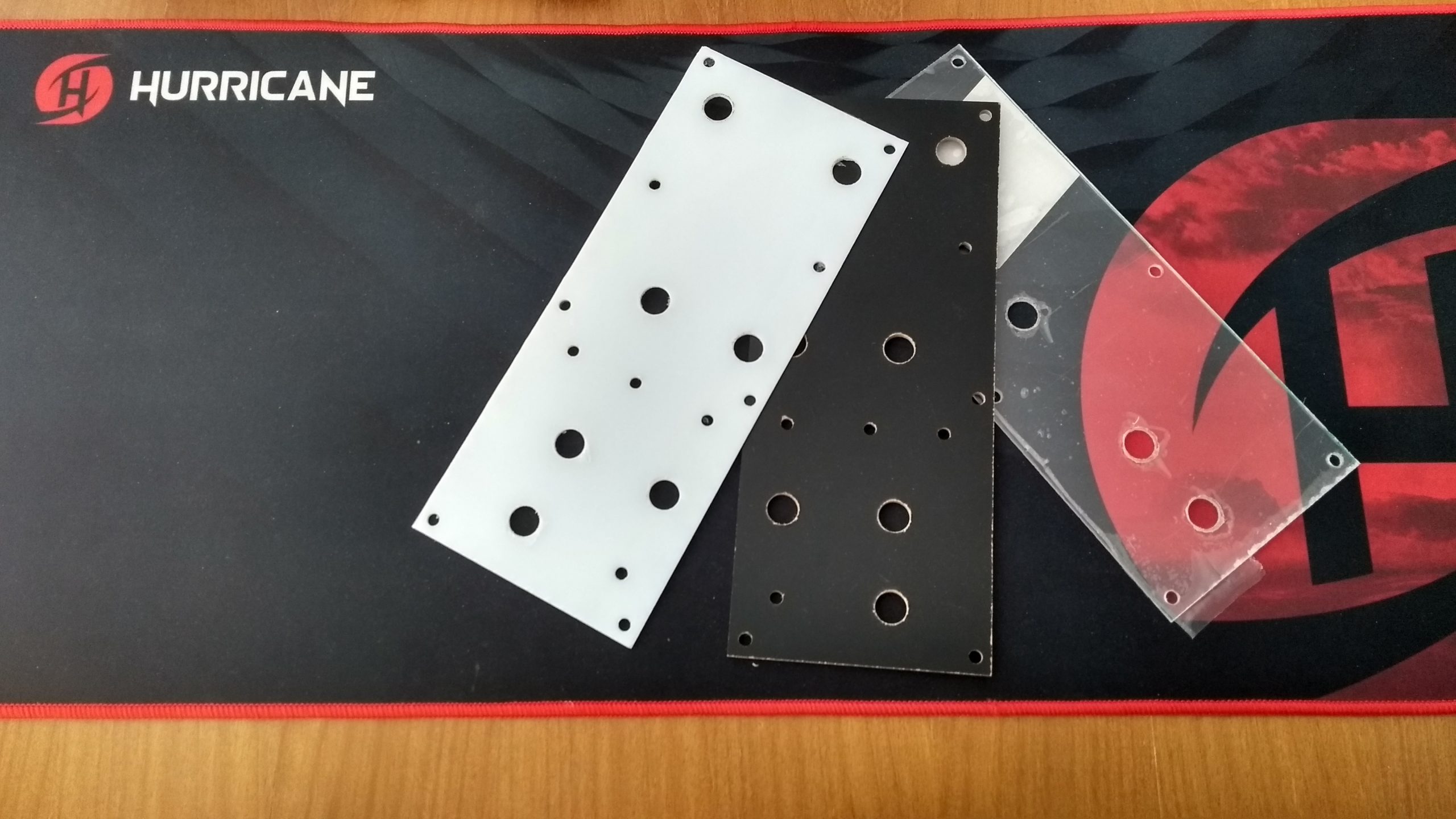
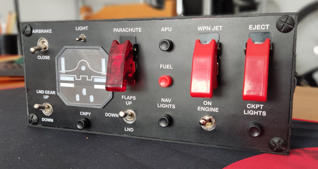
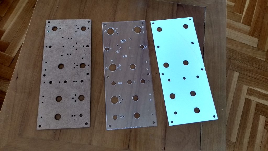
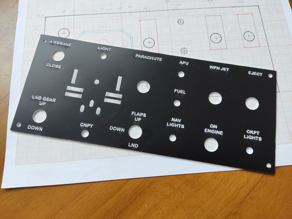
The front is made up of 3 panels. A wooden one, into which almost all switches and buttons are threaded. Another transparent methacrylate, which serves to hide the nuts of the switches. And finally an exterior one in translucent white methacrylate, which hides the previous panels. On this, I have put a white cardboard, where I have printed, in black, everything except the letters. In this way, the letters remain white and the front black.
The switches with guard are screwed to this last panel.
The front panel is screwed to some nuts inside the box. This way everything is held together. At the same time, it is easy to repair any damage, as the front and rear panels can be removed.
Also, it is backlit. Behind each word there are some green leds that illuminate the words. So it can be seen in the dark. All these leds are connected, through a switch, to the 5v pin of the arduino board. In this way, when you press the switch, all these LEDs light up.
There is another way to make the front panel. It consists of using, as a top layer, a two-layer methacrylate panel. This panel is white (better if it is translucent) but, on one side, it has a thin layer of black. What is done is to engrave the letters with a laser on this side. That makes the black color stand up, leaving the letters with the white color behind. Then, if you put LEDs on the back, the letters light up. This way is more expensive, of course, because you need someone who has a laser engraver and can do this. But it is much more professional. I found a group of makers (3KMedialab) who did it for me, although I still have the version that goes with the cardboard.
There is another set of leds, where the plane is drawn, which indicates the status of the flaps, landing gear and airbrake. These leds are also controlled by the arduino board. There is no connection between these leds and the state of the same leds in the game. They light according only to the state of the switches in the panel. If the landing gear switch is down on the panel, the landing gear lights will be on (even if in-game something went wrong and it didn’t go down). For a future version I will investigate the possibility that I can read these values from the game.
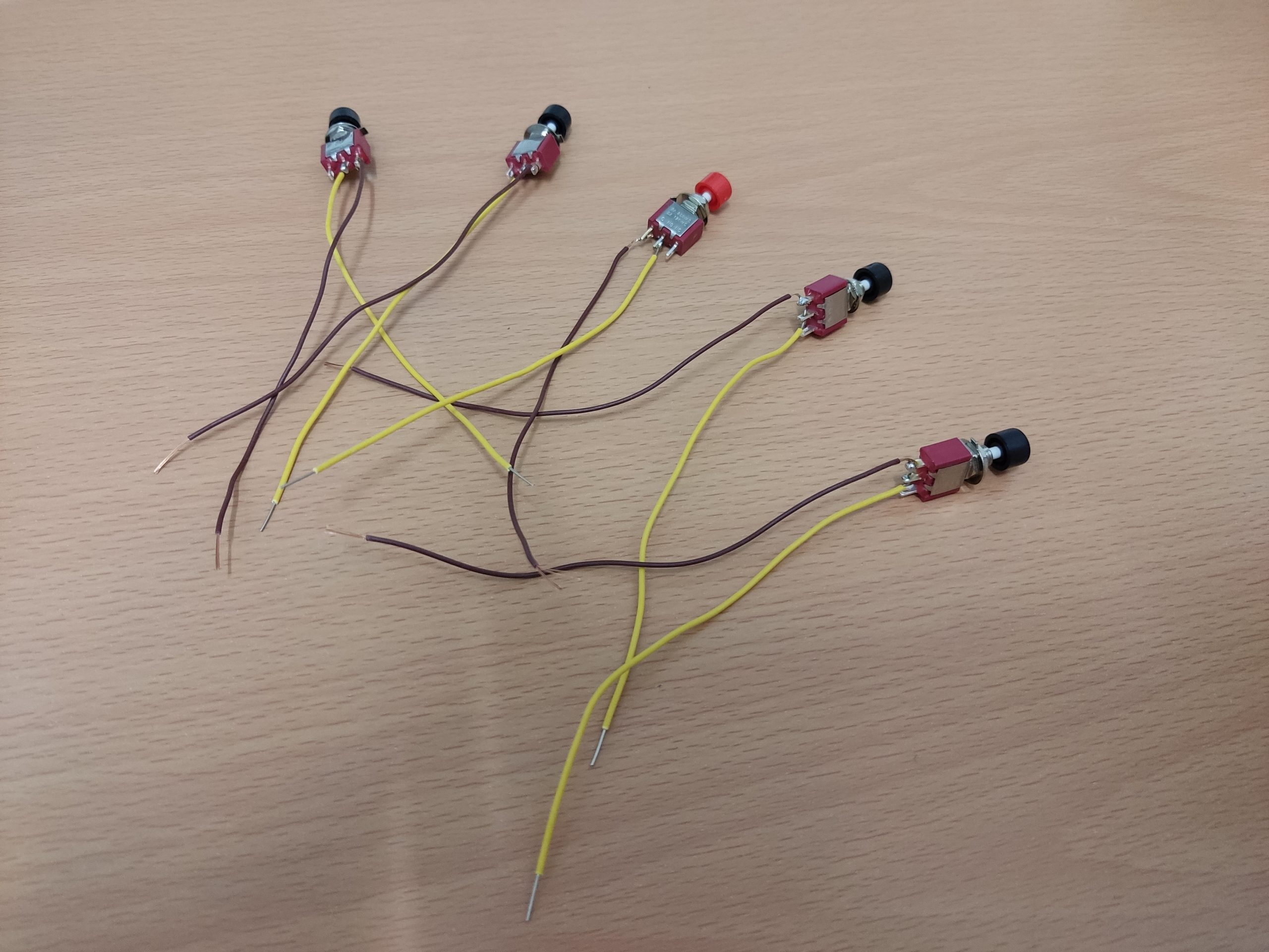
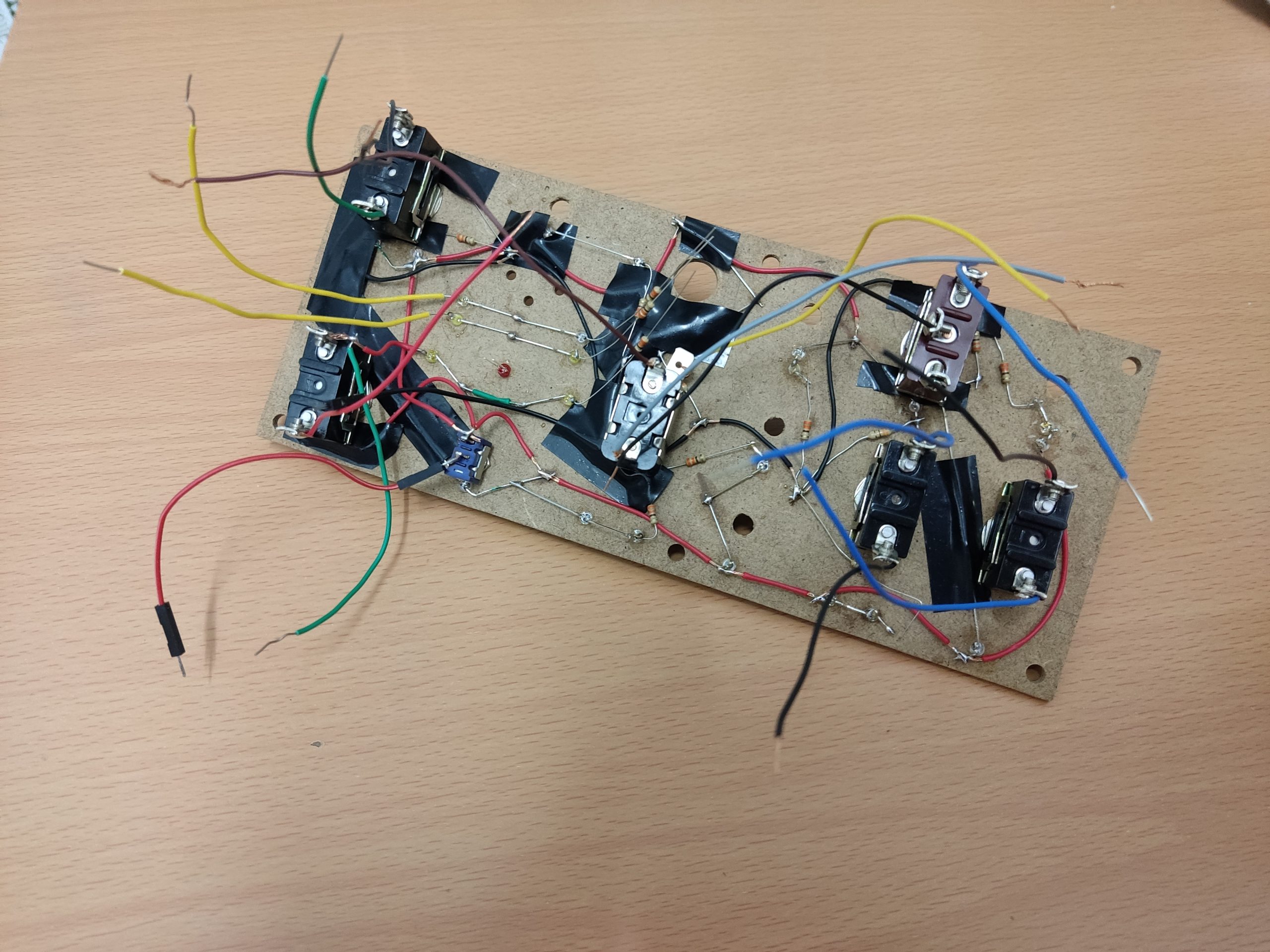
Internally there are many cables (for the buttons and for the backlit), but the truth is that the connections are very simple. Most switches and buttons have two wires; one of them connected to ground (0v) and the other to a pin of the arduino wich is in «pull-up». In this way it is very easy to read the change of state in a switch. When a switch changes state, what is done is to send to the computer an event that a certain key has been pressed (as if it were a key on the keyboard). Then, on the computer, I have a program installed that «translates» that keystroke into a keystroke of the specific key that I want (for example, the ‘L’ key). This way, when I’m playing the game and I press the navigation lights switch, what actually comes into the game is that the ‘L’ key on the keyboard has been pressed.
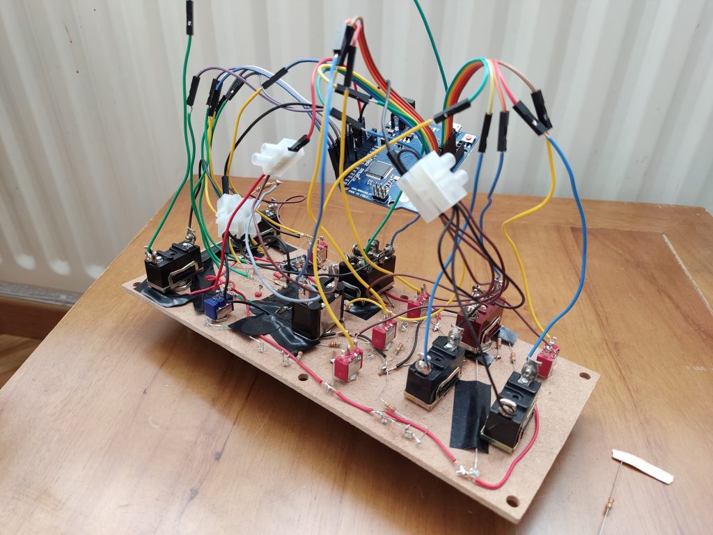
To do that, I have used the arduino «Joystick» library, which has functions to control button presses. When you press a button or switch, you call a function that sends a signal that a button has been pressed (buttons are numbered). It handles up to 32 buttons, if I’m not mistaken, and lever movements. In my case I only need to send button presses.
Another way to do this is by using the arduino «Keyboard» library, which does the same thing. I have to try this one, but it will be even easier than the previous one.
I also have to program some timers for the landing gear leds. When this switch is pressed, the timer counts down 3 seconds, in which there is a red flashing LED, and then the three landing gear LEDs turn on or off. I have programmed these timers with the arduino millis() function. There are good examples on the internet.
The airbrake and flap lights are also activated by software when the corresponding switches are pressed. Those lights doesn´t have a timer.
In my blog (in Spanish) I am going to put the whole creation process in a more detail way (plans, measurements, programming, etc), but in essence, it is as simple as I have explained here.
Of course, unforeseen problems have arisen (hotspot, paint on the box, too thick panels, screwing the front, etc), which I have solved in the best way I have found. Thanks to this I have also found several points of improvement. If I decide to make a new version of the panel (maybe in the future), I will try to carry out these improvements.
I put some photos of the panel. For any questions, you can contact me in any of the ways that are in the «contact» section of this blog.